At 11:03 A.M. on April 17, 2018, metal fatigue caused a fan blade to break off inside the left engine of Southwest flight 1380 en route from New York to Dallas at 32,000 feet. The rupture blew the exterior of the engine apart, bombarding the fuselage with metal fragments and shattering a window in row 14. In the rapid cabin decompression that followed, a passenger was sucked halfway out the damaged window and sustained fatal injuries. The pilots were able to prevent a larger tragedy by landing the plane safely in Philadelphia.
The number of airplane accidents caused by metal fatigue has been steadily increasing for years, rising to a high of 30 during the 2010s, the decade most recently tabulated. Several of these incidents were serious enough to require emergency landings. Although it seems like the Boeing 737 Max 9 door plug that popped out at 16,000 feet in January 2024 was probably missing bolts, the Max family of planes had experienced a fatigue-related safety issue in 2019, when wing slats susceptible to cracks had to be replaced.
Airplanes have been described as “two million parts flying in close formation,” and a lot can go wrong with them. Successive flights subject these parts to cycles of intense stress and relaxation, during which small defects, unavoidable in the manufacturing process, can lead to tiny cracks. Once a crack grows long enough, as one did at the base of Southwest 1380’s fan blade, adjacent components can break off. Aircraft designers therefore need to predict the maximum stress that components will have to endure.
On supporting science journalism
If you’re enjoying this article, consider supporting our award-winning journalism by subscribing. By purchasing a subscription you are helping to ensure the future of impactful stories about the discoveries and ideas shaping our world today.
Cracks can show up in structures as huge as dams, bridges and buildings and as biologically intimate as the bones and teeth in our own bodies. Engineers at the National Institute of Standards and Technology are modeling the 2021 collapse of a beachfront condominium in Florida, for instance, to understand what role cracks in the supports might have played in the disaster. And a recent analysis of the Titan submersible that imploded in the North Atlantic Ocean has identified areas that might have fractured. In metal and concrete and tooth enamel, cracks form in areas that are subjected to the most intense stresses—and they can be most dangerous when they exceed a critical length, which depends on the material.
Engineers can use similar tools to study an enormous variety of cracks and to prevent failures. As an important defense against failures, a machine or structure should be subjected to physical tests, but such testing can be expensive and may not always be feasible. Once a part is being used, it should be periodically inspected, which is also expensive.
Beyond these hands-on strategies, there is a crucial third aspect of preventing failure: computer simulation. During development, simulations help engineers create and test designs that should remain viable under many different conditions and can be optimized for factors such as strength and weight. Airplanes, for instance, need to be as light and durable as possible. Done properly, simulations can help prevent mishaps.
As the U.S. embarks on a massive program to overhaul its infrastructure, improving the reliability of computer simulations can help ensure safety.
The soundness of these simulations is essential for safety—but they don’t get the same scrutiny or regulatory oversight as manufacturing defects, maintenance errors or inspection frequency. Engineers analyzing the 1991 collapse of a Norwegian oil platform found that because of a simulation error, one of the internal supporting walls was predicted to experience only about half as much stress as it actually did. Consequently, it was designed with much lighter reinforcement than needed, and it failed.
As the U.S. embarks on a massive program to overhaul its infrastructure, ensuring safety and durability will be critical. Robust computer simulations can help with both while reducing the need for expensive physical testing. Concerningly, however, the simulations that engineers use are often not as reliable as they need to be. Mathematics is showing how to improve them in ways that could make cars, aircraft, buildings, bridges, and other objects and structures safer as well as less expensive.
Given the complexity of 21st-century machines, it’s curious that an anagram published in the 1670s underpins their mechanics. Known as Hooke’s law, ut tensio, sic vis (“as the extension, so the force”) states that the deformation of an elastic object, such as a metal spring, is proportional to the force applied to it. The law remains in effect only if the object stays elastic—that is, if it returns to its original shape when the force is removed. Hooke’s law ceases to hold when the force becomes too large.
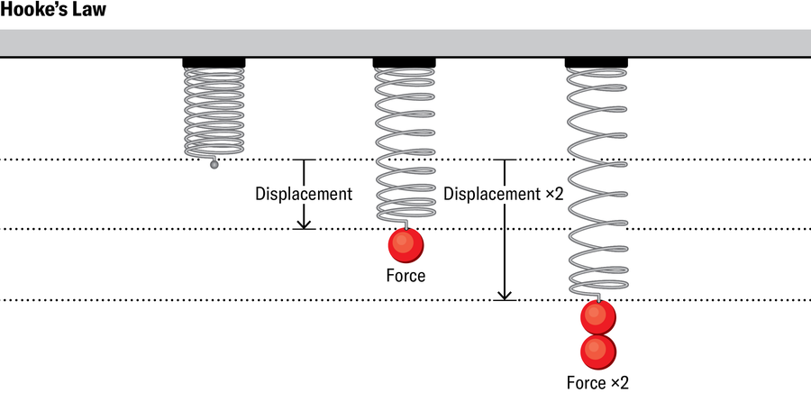
In higher dimensions, the situation gets more complicated. Imagine pressing down lightly on a cube of rubber glued to a table. In this case, the reduction of the cube’s height compared with its original height, the “strain,” is proportional to the force you apply per unit area of the cube’s top surface, the “stress.” One can also apply varying forces to the different faces at different angles—subject the cube to diverse “loadings,” as engineers say. Both the stress and the strain will then have multiple components and typically vary from point to point. A generalized form of Hooke’s law will still hold, provided the loading is not too large. It says that the stresses and strains remain proportional, albeit in a more complicated way. Doubling all the stresses will still double all the strains, for example.
People use Hooke’s law to analyze an astonishing variety of materials—metal, concrete, rubber, even bone. (The range of forces for which the law applies varies depending on the material’s elasticity.) But this law provides only one of many pieces of information needed to figure out how an object will respond to realistic loadings. Engineers also have to account for the balance of all the forces acting on the object, both internal and external, and specify how the strains are related to deformations in different directions. The equations one finally gets are called partial differential equations (PDEs), which involve the rates at which quantities such as stresses and strains change in different directions. They are far too complicated to be solved by hand or even to be solved exactly, particularly for the complex geometries encountered in, for instance, fan blades and bridge supports.
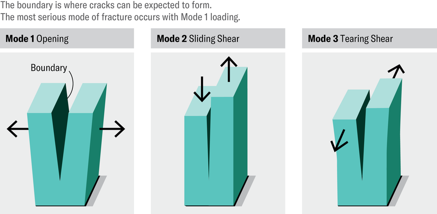
Even so, beginning with, most notably, Vladimir Kondrat’ev in 1967, mathematicians have analyzed these PDEs for common geometries such as polygons and polyhedrons to gain valuable insights. For instance, stresses will usually be highest in the vicinity of any corners and edges. That is why it’s easier to tear a sheet of foil if you first make a nick and then pull the foil apart starting from the point of the cut.
The problem is that many machine parts whose integrity is essential for safety incorporate such features in their design. Although corner tips and edges are generally rounded as much as possible, cracks are still more likely to form in these places. Loadings that pull the sides of a boundary directly apart are the most likely to expand a crack. So engineers must pay special attention to these locations and the forces acting around them to ensure that the maximum stresses the object can endure before it starts breaking apart are not exceeded.
To do so, they need to find approximate solutions to the object’s PDEs under a variety of realistic loadings. Engineers have a handy technique for this purpose, called the finite element (FE) method. In a landmark 1956 paper, engineers M. Jonathan Turner, Ray W. Clough, Harold O. Martin and L. J. Topp point out that to understand how an object deforms, it helps to think of it as being made of a number of connected parts, nowadays referred to as finite elements.
Let’s say you want to find out how a two-dimensional elastic object, such as a tautly stretched screen fixed along its perimeter, deforms when subjected to a powerful wind hitting it perpendicularly. Imagine the screen being replaced by a bunch of linked triangular facets, each of which can move and stretch but must remain a flat triangle. (One can also use a quadrilateral.) This model screen made of triangles is not the same as the original, smooth screen, but it provides a more tractable problem. Whereas for the actual screen you would need to find the displacement at each point—an infinite problem—for the model screen made of triangles you need to find only the final positions of each triangle corner. That’s a finite problem, relatively easy to solve, and all the other positions of the screen surface can be deduced from its solution.
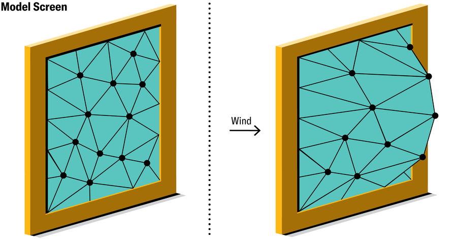
A governing principle from physics states that the screen will assume the shape for which the potential energy, which it possesses by virtue of its position or configuration, is a minimum. The same principle predicts that after a guitar string is plucked, it will eventually return to a straight-line shape. This principle holds for our simplified FE screen as well, yielding a set of relatively simple “linear” equations for the unknown displacements at the nodes. Computers are very adept at solving such equations and can tell us how the model screen deforms.
Three-dimensional objects can be similarly modeled; for these, the FEs are usually either blocks or tetrahedra, and the number of equations is typically much higher. For the modeling of an entire airplane, for instance, one might expect a problem with several million unknowns.
Although the FE method was originally developed to determine how structures behave when forces act on them, the technique is now seen as a general way to solve PDEs and is used in many other contexts as well. These include, for example, oncology (to track tumor growth), shoe manufacturing (to implement biomechanical design), film animation (to make motion more realistic, as in the 2008 Pixar movie WALL-E), and musical instrument design (to take into account the effect of vibrations in and around the instrument). Although FEs might be an unfamiliar concept to most people, one would be hard-pressed to find an area of our lives where they do not play a role.
Several applications involve the modeling of cracks. For instance, the authors of a 2018 study used FEs to explore how cracks propagate in teeth and what restorations might work best. In a different study, scientists investigated what kinds of femur fractures one can expect osteoporosis to lead to at different ages. FE simulation also helps to reveal the root cause after failures occur, as with the Florida condo collapse and the Titan implosion, and it is routine after aircraft accidents.
Drawing on their accumulated experience, engineers Richard H. MacNeal, John A. Swanson, Pedro V. Marcal, and others released several commercial FE codes in the 1970s. The best known of these “legacy” codes was originally written for NASA in the late 1960s and is now referred to as the open-source NASTRAN (short for “NASA Structural Analysis”). NASTRAN remains the go-to program for a crucial step in aeronautical design, in which engineers do a rough FE analysis of a computer model of the entire plane being designed to identify areas and components where structural problems are most likely to occur. These regions and parts are then individually analyzed in more detail to determine the maximum stress they’ll experience and how cracks may grow in them.
Questions such as whether a bolt may fracture or a fan blade may break off are answered at this individual level. Almost all such local analysis involves the legacy programs launched several decades ago, given their large market share in commercial settings. The design of the finished parts that end up in the aircraft we fly in or the automobiles we drive depends heavily on these codes. How accurate are the answers engineers are able to get from them? To find out, we need to take a deeper dive into the math.
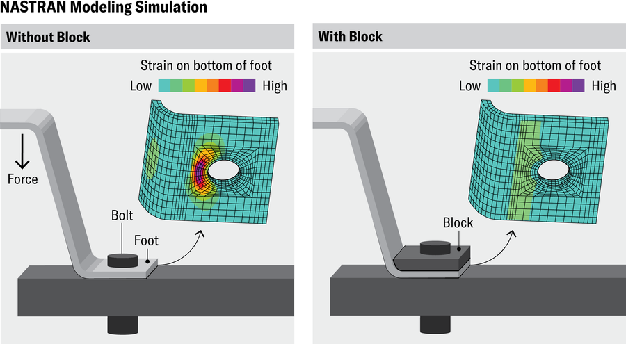
Jen Christiansen; Source: “Stress Analysis and Testing at the Marshall Space Flight Center to Study Cause and Corrective Action of Space Shuttle External Tank Stringer Failures,” by Robert J. Wingate, in 53rd AIAA/ASME/ASCE/AHS/ASC Structures, Structural Dynamics and Materials Conference Proceedings, April 2012 (reference)
Earlier, we learned how to determine the deformation of our FE model for the screen, but how close will this result be to the true deformation? A remarkable theorem, first noted by French mathematician Jean Céa in his 1964 Ph.D. thesis but rooted in the work of Russian mathematician Boris G. Galerkin, helps to answer that question. The theorem states that as long as we minimize potential energy, out of all possible deformations our FE screen can assume, the one calculated by our method will be the closest possible to the exact answer predicted by the PDEs.
By the early 1970s several mathematicians worldwide had used Céa’s theorem to prove that the difference between the FE model’s predictions and the real shape would decrease to zero as the meshes became increasingly refined, with successively smaller and more numerous elements. Mathematicians Ivo Babuška and A. Kadir Aziz, then at the College Park and Baltimore County campuses of the University of Maryland, respectively, first presented a unified FE theory, incorporating this and other basic mathematical results, in a landmark 1972 book.
But around the same time mathematicians began discovering that engineers were incorporating various modifications and “tricks” into commercial codes, which, though often violating the crucial property of energy minimization, empirically seemed to work. Mathematician Gilbert Strang of the Massachusetts Institute of Technology named such modifications “variational crimes” (“variational” comes from the calculus of variations, which is related to the FE method). Mathematicians could prove that some of these “crimes” were benign, but others had the potential to produce substantially incorrect answers.
Particularly problematic were the work-arounds used to treat a breakdown in accuracy called locking. This issue arises when the underlying elasticity equations contain a value that is close to being infinite—such as a fraction in which the thickness of an extremely thin metal plate is used as the denominator. Locking also commonly occurs in models for rubber because an elasticity value related to Hooke’s law gets very large. It was only in the 1990s that Babuška and I provided a precise definition and characterization of locking. By then several other mathematicians, most notably Franco Brezzi of the University of Pavia in Italy, had, for many problems, established which variational crimes used to deal with locking are sound and which should be avoided because they can potentially give inaccurate answers.
But all this analysis had little effect on legacy codes, where risky modifications remain. One reason is that these codes were already entrenched by the time mathematicians recommended changes, so it was impractical to incorporate them. Also, there seems to be a gap between mathematical predictions and actual practice—“shades of gray,” as Thomas J. R. Hughes, a professor of aerospace engineering at the University of Texas at Austin, puts it. “Some mathematically suspect modifications can perform better than approved ones for commonly encountered problems.”
Perhaps the biggest hurdle to incorporating safer solutions to locking was a cultural difference between the mathematical and engineering views of FE modeling. Mathematicians see the FE solution as one in a series of approximations that, under appropriate mathematical conditions, are guaranteed to converge to the exact solution. In engineering practice, however, FE modeling is a free-standing design tool that tells you how the actual object will behave when built. Rank-and-file engineers commonly learn about FEs in a couple of courses at best, typically with no mention of such things as problematic modifications. Hughes relates an anecdote in which a modeling company refused to buy a newer software product because its results did not match the answer given by NASTRAN. The clients insisted the NASTRAN solution was exact and correct. (It was only by reverse engineering the new software that its designers got it to produce answers are matching NASTRAN’s)
FE solutions can in fact be very different from the physical results they’re supposed to predict. The reasons include variational crimes, the limitations of underlying mathematical models, the exclusion of smaller features from simulations and the use of finite problems to replace the infinite one of solving a PDE. This is the case, for instance, in the preliminary analysis of large airplane components such as fuselages and wings. Engineers have to use past experimental results to “tune” the FE output before they can figure out what the true prediction is. Such accumulated wisdom is essential in interpreting FE results for new designs that haven’t yet been physically tested.
The strength analysis of smaller parts, such as lugs and fasteners, can present more of a problem because there are often no physical data available to tune things with. A 2022 challenge problem involving crack analysis, circulated by a major aerospace company to four contracting organizations that use legacy codes, found that the results from three groups diverged strikingly from the true, experimentally determined solution. The computations showed a crack growing much more slowly than it actually did, leading to a predicted safety margin that was disconcertingly inflated.
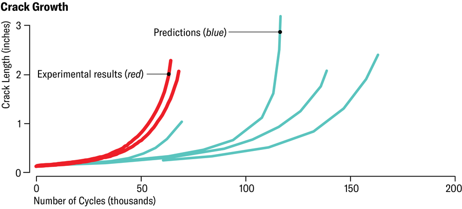
Jen Christiansen; Source: “The Demarcation Problem in the Applied Sciences,” by Barna Szabó and Ricardo Actis, in Computers & Mathematics with Applications, Vol. 1632; May 2024 (data)
Other such challenge problems have shown that inaccurate codes are not necessarily the core issue—participants often made simplifying assumptions that were invalid or selected the wrong type of element out of the multitude of available variations of the original triangle and quadrilateral. Such errors can be expensive: the 1991 collapse of the Norwegian oil platform mentioned earlier caused damages amounting to more than $1.6 billion in today’s dollars. Simulation shortcomings have also been implicated in the F-35 fighter plane’s many fatigue and crack problems, which have contributed to its massive cost overruns and delays. In general, the less certainty one can ascribe to computational results, the more frequently expensive inspections must be carried out.
The problem of estimating how reliable a simulation is might seem hopeless. If we don’t know the exact solution to our computer model of, say, an airplane component, how can we possibly gauge the error in any approximate solution? But we do know something about the solution: it satisfies the partial differential equations for the object. We cannot solve the PDEs, but we can use them to check how well a candidate solution works—a far easier problem. If the unknown exact solutionwere plugged into the PDE, it would simply yield 0. An approximate solution will instead give us a remainder or “residual,” typically called R—a measure of how good the solution is.
Further, because the object is being modeled by finite elements that can deform only in certain ways, the calculated stresses will not vary smoothly as they do in reality but jump between the boundaries of the elements. These jumps can also be calculated from the approximate solution. Once we compute the residuals and jumps, we can estimate the error across any element using techniques that Babuška and Werner C. Rheinboldt of the University of Pittsburgh, along with other mathematicians, started developing in the late 1970s. Since then, other strategies for estimating the errors of FE analyses have also been developed.
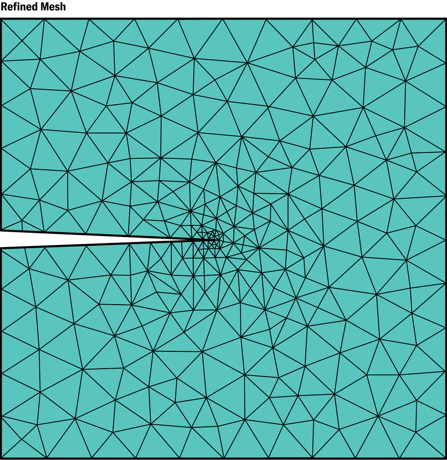
Estimating the error has several benefits. First, because the inclusion of smaller and more numerous elements generally improves the accuracy, you can program your code to automatically generate, in successive steps, smaller elements in regions where the error is likely to be large. We already saw from the mathematical analysis of PDEs that the stresses increase very rapidly near corners and edges. This phenomenon also makes the error highest in such regions. Instead of manually creating finer meshes in such critical locations, this step can be taken care of automatically.
Second, the estimated overall error can help engineers gauge how accurate the calculated values are for quantities they’re interested in, such as the stress intensity in a critical area or the deformation at a particular point. Often engineers want the error to be within a certain margin (from less than 2 to 10 percent, depending on the field). Unfortunately, most algorithms overestimate or underestimate the error, so it is difficult to say how good the boundthey provide really is. This aspect remains an active area of research. Even so, error estimation, had it been used, almost certainly would have alerted engineers about the problem with their FE model for the Norwegian oil platform.
A better way to estimate overall error—that is, to assess the reliability of a computed solution—is to use a different philosophy for the FE method: the so-called p refinement, first developed by engineer Barna Szabó of Washington University in St. Louis in the 1970s. The usual way to increase accuracy is called h refinement because the mesh is successively refined through reduction of a typical element’s width, denoted by h. For p refinement, we stick with just one mesh throughout but increase accuracy by allowing each triangle to deform in additional ways instead of always remaining flat. In the first step, the method allows a straight line in any triangle to bend into a parabola, and then, step by step, lines transition into ever more complex curves. This modification gives each element increasing wiggle room, allowing it to match the shape of the solution better at each step. Mathematically, this process amounts to increasing the degree p of the underlying polynomials, the algebraic formulas used to denote different types of curves.

As Babuška and his colleagues, including me, have shown, p refinement converges to the exact solution of the PDEs faster than the traditional h method for a wide class of problems. I have also helped prove mathematically that the p version is free of locking problems, so it doesn’t need any of the modifications used for the h method. Further, the succession of wiggling shapes turns out to offer an easy and dependable way to assess reliability.
Discouragingly, however, neither the p nor the h method of assessing reliability plays a prominent role in the legacy codes from the 1970s used to this day. The reason might be that the programs were designed and became culturally entrenched before these advances came along. Among newer industrial codes, the program StressCheck is based on the p version and does provide reliability estimates.
Such estimation offers a further benefit when experimental results are available for comparison: the ability to assess the difference between physical reality and the PDEs used to model it. If you know the FE analysis is accurate but your overall error is still large, then you can start using more complex models, such as those based on physics where proportionality no longer holds, to bridge the gap. Ideally, any underlying mathematical model should be validated through such comparisons with reality.
The advent of artificial intelligence most likely will change the practice of computer simulation. To begin with, simulation will become more widely available. A common goal of commercial AI programs is to “democratize” FE modeling, opening it up to users who might have little intrinsic expertise in the field. Automated chatbots or virtual assistants, for instance, can help guide a simulation. Depending on how thoroughly such assistants have been trained, they could be a valuable resource, especially for novice engineers. In the best case, the assistant will respond to queries made in ordinary language, rather than requiring technical or formatted phrasing, and will help the user choose from the often dizzying array of elements available while giving adequate alerts about mathematically suspect modifications.
Another way AI can be effective is in generating meshes, which can be expensive when done by a human user, especially for the fine meshes needed near corners, crack tips, and other features. Mathematicians have determined precise rules for designing meshes in such areas in both two and three dimensions. These rules can be exceedingly difficult to input manually but should be fairly easy to use with AI. Future codes should be able to automatically identify areas of high stress and mesh accordingly.
A more nascent effort involves supplanting FE analysis entirely by using machine learning to solve PDEs. The idea is roughly to train a neural network to minimize the residual R, thereby constructing a series of increasingly accurate predictions of the displacements for a set of loadings. This method performs poorly with crack problems because of high localized stresses near the crack tips, but researchers are finding that if they incorporate information about the exact nature of the solution (by, for instance, using the mathematical work of Kondrat’ev), the method can be viable.
In the midst of these and other potentially game-changing AI initiatives, the decidedly unflashy task of assessing the reliability of computations, so crucial to all these advances, is not being sufficiently addressed. Stakeholders should look to NASA’s requirements for such reliability. These include demonstrating, by error estimation and other means, that the underlying physics is valid for the real-life situation being modeled and that approximations such as FE solutions are within an acceptable range of the true solution of the PDEs.
NASA first codified these requirements into a technical handbook as a response to the Columbia space shuttle disaster. The prospect of human expertise and supervision dwindling in the future should be no less of a wake-up call. Dependable safeguards for reliability need to be built in if we are to trust the simulation results AI delivers. Such safeguards are already available thanks to mathematical advances. We need to incorporate them into all aspects of numerical simulation to keep aviation and other engineering endeavors safe in an increasingly challenging world.
